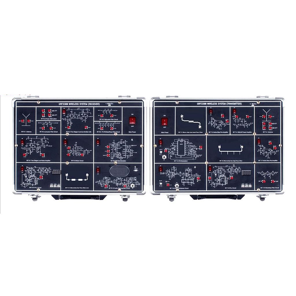
Gw Instek GRF-3300S RF 교육 시스템
생산업체: GW INSTEK Model: GRF-3300S - 연락처
Features
-
Designed for wireless frequency range applications
-
Includes a 880MHz Digital PLL and 2.4GHz microstrip line filter circuits
-
Include these applications of RF Transmitter and Receiver both
-
Training for the Voice Communication System
-
Demonstrates the applications and measurements for using spectrum analyzers in communication instruments
-
Specific RF circuit characteristics & PCB Layout on each module
-
Training system covering 22 modules, and over 50 experiments
-
Spectrum Analyzer & RF Training System
The GRF-3300S training system is designed for a high frequency range of wireless applications.This superior system is equipped with digital phase-locked loop (PLL) and a microstrip line filter (MLF) with a design range from 730MHz up to 960MHz / 2.4 GHz,
which is increasingly important in the education field. By using the Wireless Voice Communication system, students can practically complement their learning.
The GRF-3300S with the combination of a training syllabus, basic theory, systematic demonstrations, and hands-on experiments make it the perfect match for modern RF communication education.The spectrum analyzer used in the training system is not only capable of experimenting with measurement testing, but is also a standard industrial instrument itself,
making it practical for students to adapt in the occupational field.
-
Training Contents
Sections
Theory
Experiment
Related Applications
The Fundamentals
Impedance matching network: L-type, π-type, T-type
Smith chart: theory and practical examplesTheory explaining
RF Component Test
Antenna
Antenna parameter, antenna structure, antenna type
Frequency response
Antenna Design
Attenuator
Attenuator parameter, attenuator type, attenuator design
Attenuation characteristics
When the Signal is Too Big
Low Noise Amplifier
LNA parameter, 1dB compression point, LNA structure
Input and output return loss, amplifier gain, 1dB compression point
Small Signal Enlarged
Preamplifier
Preamplifier type, preamplifier structure
Input and output return loss, amplifier gain, 1dB compression point
Small Signal Enlarged
Power Amplifier
Power amplifier frequency characteristics, bias circuit, power amplifier parameter, power amplifier structure
Gain flatness, 1dB compression point, fundamentals to harmonics ratio
Power Enlarge
Filter
Filter parameter, filter structure: Butterworth, Chebyshev
Input/output return loss, insertion loss
EMI filter Design
Mixer
Mixer structure, mixer parameter, mixer type
Conversion gain, 1dB compression point, isolation
TV Tuner
Phase Locked Loop
PLL structure, frequency synthesizer, PLL controller, loop filter, design a PLL
Frequency response/modulation
Signal Generator
Audio Processor
Audio compression/decompression circuit
Pre-emphasis, compression characteristics, expander and de-emphasis, decompression characteristics
Wireless Microphone
Modulation
Design and implement a modulation circuit
Frequency modulation
Remote Controller
Demodulation
Design and implement an FM intermediate frequency demodulation circuit
IF modulation, RSSI output
Broadcasting
Transmitter
Transmitter parameter, transmitter structure
Transmission spectrum
Radio Set
Receiver
Receiver parameter, receiver structure
Receiving signal spectrum, demodulation waveform
Radio Set
Voice Demo
Combine with transmitter & receiver circuits
Voice communication system
VoIP
Microstrip Line Filter
Transmission line basics, stepped-impedance LPF, coupled line BPF, optimized HPF
Insertion loss
RFID
POWER SOURCE
AC 110V or 220V, 50/60Hz
DIMENSIONS & WEIGHT
GRF-3300S
428(W) x 90(H) x 303(D)mm for Transmitter & Receiver, Approx. 8.4kg
-
Include
- Teacher book & Student book
50 Terminator
AC Power cord (only for GRF-3300S) x 2
Antenna x 2
Microphone
N-SMA Adaptor x 3
Return loss bridge
RF Cable, 10cm x 6
RF Cable, 20cm x 6
RF Cable, 75cm x 3
SMA-SMA Connector
- Teacher book & Student book
Features
-
Designed for wireless frequency range applications
-
Includes a 880MHz Digital PLL and 2.4GHz microstrip line filter circuits
-
Include these applications of RF Transmitter and Receiver both
-
Training for the Voice Communication System
-
Demonstrates the applications and measurements for using spectrum analyzers in communication instruments
-
Specific RF circuit characteristics & PCB Layout on each module
-
Training system covering 22 modules, and over 50 experiments
-
Spectrum Analyzer & RF Training System
The GRF-3300S training system is designed for a high frequency range of wireless applications.This superior system is equipped with digital phase-locked loop (PLL) and a microstrip line filter (MLF) with a design range from 730MHz up to 960MHz / 2.4 GHz,
which is increasingly important in the education field. By using the Wireless Voice Communication system, students can practically complement their learning.
The GRF-3300S with the combination of a training syllabus, basic theory, systematic demonstrations, and hands-on experiments make it the perfect match for modern RF communication education.The spectrum analyzer used in the training system is not only capable of experimenting with measurement testing, but is also a standard industrial instrument itself,
making it practical for students to adapt in the occupational field.
-
<td style="border: rgb(236,Training ContentsSectionsTheoryExperimentRelated ApplicationsThe FundamentalsImpedance matching network: L-type, π-type, T-type
Smith chart: theory and practical examplesTheory explainingRF Component TestAntennaAntenna parameter, antenna structure, antenna typeFrequency responseAntenna DesignAttenuatorAttenuator parameter, attenuator type, attenuator designAttenuation characteristicsWhen the Signal is Too BigLow Noise AmplifierLNA parameter, 1dB compression point, LNA structureInput and output return loss, amplifier gain, 1dB compression pointSmall Signal EnlargedPreamplifierPreamplifier type, preamplifier structureInput and output return loss, amplifier gain, 1dB compression pointSmall Signal EnlargedPower AmplifierPower amplifier frequency characteristics, bias circuit, power amplifier parameter, power amplifier structureGain flatness, 1dB compression point, fundamentals to harmonics ratioPower Enlarge
- 품질 보증
- 공인 보증
- 집으로 배달
- 간단하게 거래하기