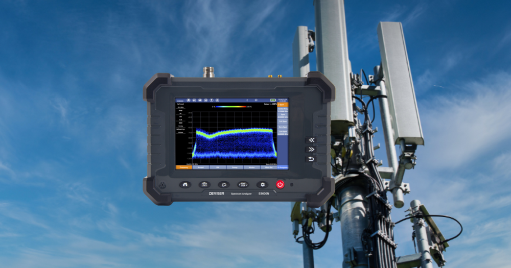
RF Signal generator
Integrating RF Signal Generators into ATE Systems
In the modern electronics manufacturing environment, the manual testing of individual components or RF modules consumes time and is prone to errors. Automated Test Equipment (ATE) systems with the capability to integrate precise RF signal generators are the key solution to enhance performance, ensure product quality, and minimize costs. This article will delve into the technical aspects, processes, and challenges when putting an RF signal generator into operation within a complete ATE line.

1. Defining Technical Requirements for Signal Generation Devices in ATE
Before integration, it is important to analyze the signal performance requirements in detail. It is necessary to clearly determine the operating frequency range, the required output power level, and the signal modulation types that the system needs to generate (e.g., amplitude modulation, frequency modulation, or more complex modulation forms such as QAM). Signal spectral purity, phase noise levels, and frequency stability are decisive factors for test quality, directly affecting the measurement results of the device under test.
The response speed capability of the generator is also a factor that cannot be overlooked. In a mass-production ATE environment, the switching time between signal parameters needs to be extremely fast to shorten the test cycle. Furthermore, the control interface must be compatible with common industrial standards such as GPIB, USB, or LAN, allowing the ATE software to communicate with and control the device smoothly, without encountering errors.
2. Selecting Protocols and Control Methods for the Generator
The physical connection and software communication between the RF signal generator and the ATE controller is a critical step. For systems requiring high speed and short distances, the GPIB interface remains a reliable choice. However, following the trend of distributed testing and remote control, Ethernet connections via the TCP/IP protocol are becoming increasingly popular thanks to their ability to transmit data significantly faster, more stably, and more flexibly.
The choice of programming language for the ATE control software also affects the integration process. Development environments such as LabVIEW and Python, with specialized IVI or SCPI libraries, provide powerful toolkits to create control commands, read data, and process responses from the generator. Engineers need to ensure that the control library (driver) of the signal generator is fully compatible with the software platform being used, avoiding conflicts or functional limitations.
Related article: What is a signal generator and why is this device almost always present in the lab?
3. Signal Synchronization and Electromagnetic Interference Management in Practice
In a complex ATE system, signal synchronization between the generator and other measurement devices is the decisive factor for the accuracy of the entire measurement.
Practical example: when testing the Error Vector Magnitude (EVM) of a Wi-Fi transmitter, the RF signal generator provides the input signal and the spectrum analyzer captures the output signal. If these two devices are not synchronized in reference frequency, the EVM results will be seriously deviated, leading to an incorrect assessment of product quality. High-end RF signal generators often feature a 10 MHz frequency reference port or a trigger port to ensure all devices operate on the same time base, avoiding such errors.
Testing environments often contain many electronic devices, harboring the potential risk of electromagnetic interference generation. In factories, it is common to see RF signal cables running near the AC power cables of motors or high-power equipment. This is a typical scenario causing conducted interference and radiated interference. The layout of signal cables, power cables, and control cables needs to strictly adhere to electromagnetic compatibility (EMC) principles. Using high-quality coaxial cables with effective shielding layers, routing wires as short as possible, and avoiding ground loops are necessary measures to protect the test signal from distortion, ensuring measurement results are always accurate and repeatable.
Reference the current signal generator lines we are distributing genuinely:
View fully at: RF Signal Generators
4. Building Automated Test Procedures and Data Processing
After integrating hardware and software, building automated test sequences is the final step. This process includes defining test steps, execution order, required signal parameters for each step, and product acceptance/rejection thresholds. The ATE software will automatically configure the signal generator, send test signals to the device under test, collect response data from measurement devices, and provide analysis results.
The ATE system needs the capability to automatically store test data, generate reports, and perform statistical analysis. This data provides an overview of product quality, helping to detect error trends early in production and support the process improvement workflow. An effective data management system will turn raw information into valuable knowledge, helping engineers easily monitor line performance and make timely decisions.
Above are the detailed analyses of the process and technical factors necessary to integrate an RF signal generator into an automated test system. Applying ATE not only optimizes complex measurements, enhances testing productivity, and minimizes errors due to human factors, but also provides valuable data to continuously improve the production process. Hopefully, this sharing will support engineers in effectively deploying and operating modern test systems.
-
-
-
-
-
-
-
-
-
-
-
-
-
-
-
-
-
-
-
-
-
-
-
-
